
Building a shoulder lamp

Tools used in this tutorial
Dremel
Dril, drill bits 2.5mm,3.5mm, 5.5mm, 6.0mm, 6.5mm
Glue Gun
Soldering Iron
Allen Keys, Screwdrivers
10mm Spanner
Stanley Knife
Sand Paper
Step 1
Here is the new video tutorial for building your Shoulder Lamp.
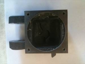
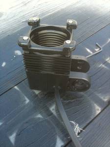
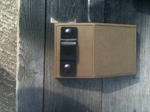
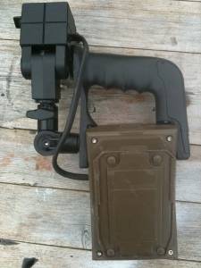
First, start with the box. It should fit together quite snugly and should have the corner bolts pre-drilled and the heli-coil inserts in place.
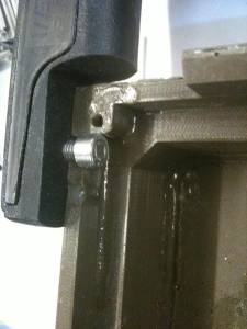
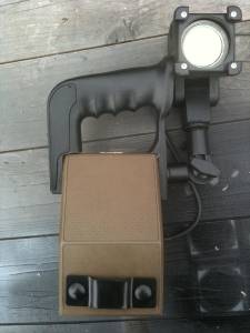
The Handle needs to be secured to the box. To do this you need to drill through the handle and the box wall with the 5.5mm drill bit. Line the handle up in the correct place on the box and drill through the handle and box wall.
The hole should be roughly in the area shown here.
Step 2
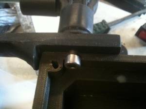
Drill the holes in the main box out to 6.5mm to allow the bolts to pass through freely.
Do the same with the lamp unit side part of the handle.
Insert the short 6mm bolt into the 5.5mm hole and wind the bolt in, cutting the thread.
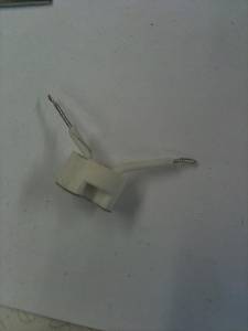
Next on to the arm swivels and lamp arm.
These should come with the M6 steel reinforcement bar already embedded into them.
Step 3
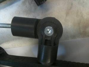
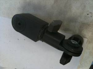
The shorter swivel (the one with the step in it) is the one that comes out of the box, and the longer one goes vertically to the main lamp head arm.
Drill the centres of the swivels with the 6mm drill bit. These will have an aluminium reinforcement strip in. The bolts can then be inserted through both the swivels and join them at a right angle.
The bolt head can be drilled (part way through) with the 5.5mm drill and then tightened on to the bolt.
Glueing the swivels in place is advised.
Step 4
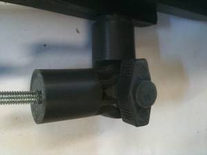
The Lower swivel nut is located on the front, and the upper nut is placed on the rear of the swivel.
The Lamp Head arm is then glued on to the top of the vertical swivel. You will need to drill a 6mm guide hole for this.
You should end up with something like this.
Step 6
The Lamp Head…
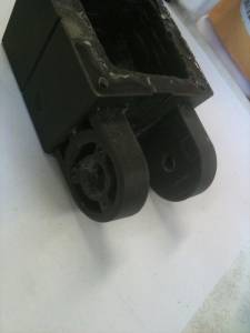
First you need to drill the pivot holes. Use the 5.5mm drill to drill through the open leg side, then the lamp arm, and then in to the closed leg side. DO NOT go all the way through the closed leg side.
This picture below shows the OPEN leg side.
Step 7
With the hole in place, open the open leg side hole out to 6mm, insert the long bolt through and cut the threads in the closed leg side.
You may need to trim the holes to allow the bolt heads to sit flush.
With this done, you should be able to place the head on the arm. It should pivot freely, but tighten up when the bolt is tightened. Do not over tighten or you will strip the threads.
Step 8
Next, using one of the aluminium vanes as a guide. Drill the corner holes with the 2.5mm drill bit. Insert the long 3mm bolts and cut the threads. Remove and set aside for later..
Step 9
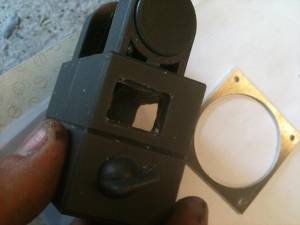
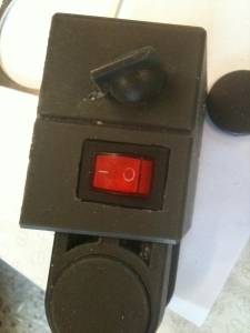
The lamp head comes cast with a faux switch, for those who do not require a working lamp.
If you do, then you need to replace this with the real switch.
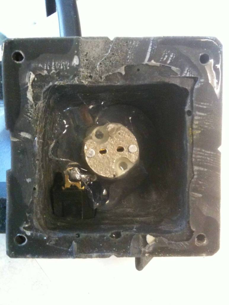
Dremel out the faux switch and make sure the real switch fits nice and snugly.
Step 10
Now on to the electrics. This is probably the most fiddly bit. So take your time. Measure twice, cut once.
The tails on the bulb holder need to be cut quite short to keep everything tidy in the head.
You may need to trim out extra bits inside the head to allow for your wires. There are already some channels cut as a guide.
Step 11
One of the tails from the holder goes to the positive pole on the switch.
The other tails is soldered to the Box wire.
The second wire on the Box wire is then soldered to the negative pole.
When it’s all in place and working (always best to do a circuit test at this stage to make sure your wiring is correct) then the bulb holder needs to be hot glued into place.
You can use some small headed self tapping screws too, and just screw the bulb holder into the head.
Insert the bulb into the holder, and then place a blob of hot glue underneath the holder and press it into place. (keep it central). When that has dried, remove the bulb and give a liberal dose of hot glue around the holder to secure it in place.

Step 12
Then add the vanes. This is best done with the bulb in place (it’s a bit tricky getting the bulb in afterwards). Use 1 of the rubber o-rings between each of the vanes, except between the last vane and the outer, where there are 2.
The detail bits are added last and the bolts go through all of it and screw into the head. These can be gently tightened.
Please note, the picture below shows 7 vanes. My mistake. The screen ones had 6 (as included in the kit) and the main front part. Apologies for any confusion.
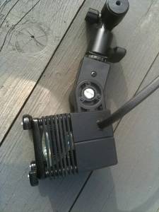
Step 13
You’ll end up with something like this.
Step 14
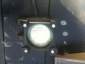
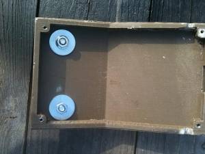
The brackets for the box are secured on to the main box using the large repair washers to spread the load across the box face.
Drill the bracket and through the box face with the 6mm drill and then square out the holes on the bracket with a needle file, so the coach bolts sit nice and flush in the holes.
Step 15
Add it all together to end up with the completed lamp.
